4-bit Full Adder (Structural Style)
4-bit Full Adder circuit is used to add two 4-bit numbers along with Carry,if any, and generates 4-bit output Sum and 1-bit Carry out.

In the following VHDL example, for testing, only four input conditions (four 4-bit Numbers ) are considered.
VHDL Code:
library IEEE;
use IEEE.STD_LOGIC_1164.ALL;
entity FA_4 is
Port ( A : in STD_LOGIC_VECTOR (3 downto 0);
B : in STD_LOGIC_VECTOR (3 downto 0);
Cin : in STD_LOGIC;
Sout : out STD_LOGIC_VECTOR (3 downto 0);
Cout : out STD_LOGIC);
end FA_4;
architecture Behavioral of FA_4 is
component FA is
port(A,B,Cin : in STD_LOGIC;
S,C : out STD_LOGIC);
end component;
signal c1,c2,c3 : STD_LOGIC;
begin
FA1: fa port map(A(0),B(0),Cin,Sout(0),c1);
FA2: fa port map(A(1),B(1),C1,Sout(1),c2);
FA3: fa port map(A(2),B(2),C2,Sout(2),c3);
FA4: fa port map(A(3),B(3),C3,Sout(3),Cout);
end Behavioral;
VHDL Code for Component:
library IEEE;
use IEEE.STD_LOGIC_1164.ALL;
entity FA is
Port ( A,B,Cin : in STD_LOGIC;
S,C : out STD_LOGIC);
end FA;
architecture Behavioral of FA is
begin
S <= A xor B xor Cin;
C <= (A and B) or (B and Cin) or (A and Cin);
end Behavioral;
use IEEE.STD_LOGIC_1164.ALL;
entity FA is
Port ( A,B,Cin : in STD_LOGIC;
S,C : out STD_LOGIC);
end FA;
architecture Behavioral of FA is
begin
S <= A xor B xor Cin;
C <= (A and B) or (B and Cin) or (A and Cin);
end Behavioral;
Testbench:
LIBRARY ieee;
USE ieee.std_logic_1164.ALL;
ENTITY FA_4_tb IS
END FA_4_tb;
ARCHITECTURE behavior OF FA_4_tb IS
-- Component Declaration for the Unit Under Test (UUT)
COMPONENT FA_4
PORT(
A : IN std_logic_vector(3 downto 0);
B : IN std_logic_vector(3 downto 0);
Cin : IN std_logic;
Sout : OUT std_logic_vector(3 downto 0);
Cout : OUT std_logic
);
END COMPONENT;
--Inputs
signal A : std_logic_vector(3 downto 0) := (others => '0');
signal B : std_logic_vector(3 downto 0) := (others => '0');
signal Cin : std_logic := '0';
--Outputs
signal Sout : std_logic_vector(3 downto 0);
signal Cout : std_logic;
BEGIN
-- Instantiate the Unit Under Test (UUT)
uut: FA_4 PORT MAP (
A => A,
B => B,
Cin => Cin,
Sout => Sout,
Cout => Cout
);
-- Stimulus process
stim_proc: process
begin
A <= "1010"; B <="0101"; Cin <='0';
wait for 10 ns;
A <= "1110"; B <="1001"; Cin <='1';
wait for 10 ns;
A <= "1011"; B <="0111"; Cin <='0';
wait for 10 ns;
A <= "1111"; B <="1000"; Cin <='1';
wait for 10 ns;
end process;
END;
Output:
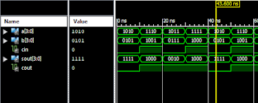
The above code is tested on Xilinx ISE Design Suite 14.7 Webpack.
It is intended only for educational purpose.


Comments
Post a Comment